
In this final OilChat of 2018 we debate a rather controversial topic: Fuel Economy vs Wear in engines. It is often believed engine oils that increase fuel economy reduce friction and therefore prolong engine life. This theory is challenged in our newsletter.
To start off we should face the fact that many drivers do not really care about fuel economy. This is confirmed by the number of SUVs, 4X4s, Double Cabs and Bakkies we see on the road. The size and weight of these vehicles are not conducive to great fuel economy. Furthermore, consider how most vehicles are driven. Anyone driving slower than the speed limit to conserve fuel is a danger to himself and other drivers that are not all that concerned about saving fuel and drive at higher speeds.
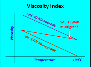
Vehicle manufacturers, on the other hand, are very concerned about fuel economy. Thinner, low viscosity oils are nowadays being used for three reasons: They save fuel in test engines, viscosity rules have changed, and vehicle manufacturers are recommending thinner grades. Traditionally SAE 20W-50 and SAE 15W-40 multigrade engine oils were used, but today many manufacturers recommend oils as thin as SAE 5W-30 and even SAE 5W-20. This seems ridiculous. SUVs and LDVs, with their brick-like aerodynamics and inherently less efficient four-wheel drive configurations, need powerful, fuel-guzzling engines to move their weight around and vehicle manufacturers recommend thin oils to save some fuel.
Thinner oils have less drag, and therefore less friction and wear. Correct? Perhaps this is true in test engines or engines in light-duty operation. Thicker oils, however, may offer better protection for more severe operations such as driving over mountains, towing a trailer or caravan, overloading, high-speed driving, overheating or dusty conditions. Any abrasive particles (such as dust/sand) equal to or larger than the oil film thickness will cause wear. Filters are necessary to keep out larger oil contaminants. The other side of the equation is oil film thickness. Thicker oil films can accommodate larger contaminants.
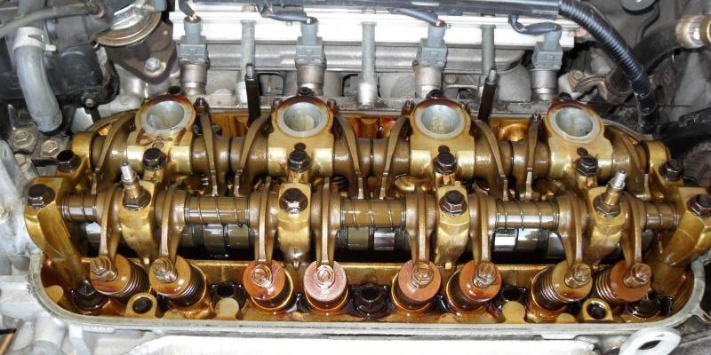
To make things worse, modern engine oils must have lower SAPS (sulphated ash, phosphorus, and sulphur) levels since high SAPS oils can damage catalytic converters. Phosphorus is part of the zinc phosphate (ZDDP) anti-wear additive. To reduce SAPS you need to reduce the amount of antiwear additive in the oil. Antiwear additives are important in the absence of a hydrodynamic oil film, such as in the valve drive train (please refer to OilChat #22). On the other hand, if engine wear causes oil consumption to increase, the risk of forming phosphorus deposits in the converter increases dramatically. It, therefore, seems that preventing wear and oil consumption should be a priority. In the past, oil formulators could make a premium product by simply adding more ZDDP. A similar move today would result in an oil formulation that would not support new vehicle warranties.
As wear increases, the efficiency of an engine declines. Valve drive train wear changes valve timing and movement. Ring and liner wear affect compression. The wear reduces fuel efficiency and power output. Efficiency continues to decline as wear progresses. Perhaps optimizing wear protection is the way to reduce fuel consumption over the entire life of the engine? Certainly, engines that have experienced significant ring and liner wear benefit from thicker oils. The use of thicker oil results in compression increase, performance improvement, and reduced oil consumption.
High-mileage lubricants are a relatively new category of engine oils. These products typically contain more detergent/dispersant and antiwear additives than ‘modern’ engine oils. They also contain a seal swell agent (to reduce oil leaks) and are available in thicker viscosity grades than most vehicle manufacturers recommend for new vehicles. Perhaps high mileage may be better described by as soon as your vehicle is out of warranty?
Although thinner oils with less antiwear additive outperform more robust products in fuel economy tests, it is not clear that such products save fuel over the life of the engine. Every engine oil is a compromise. Oils recommended by vehicle manufacturers seem to compromise wear protection under severe conditions to gain fuel economy and catalyst durability. It is important to recognize that the use of engine oil that offers more wear protection will most likely compromise your warranty. Thicker oils also compromise cold temperature flow, which may be of concern, depending upon climate and season.
For out of warranty engines in Southern Africa, the best protection against wear is probably a product that is a little thicker (SAE 10W-40 or even SAE 15W-40) and with more antiwear additives than the oils that support the manufacturer’s warranty.
The best oil for your vehicle depends on your driving habits, the age of the engine, operating conditions and the climate you drive in, but it is not necessarily the type of oil specified in the owner’s manual. If in doubt our experts are at your disposal and ready to provide you with advice and guidance. Simply mail us at info@bcl.co.za.
We would also like to make use of this opportunity to wish all our readers a wonderful Festive Season and a prosperous New Year. We are certainly looking forward to chatting with you again in2019.


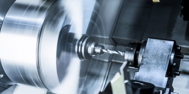

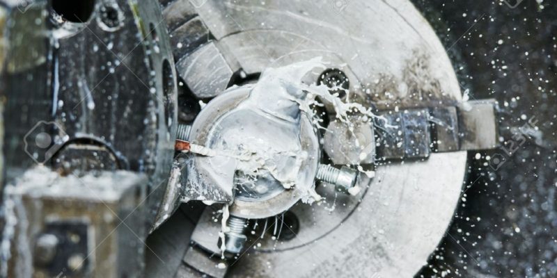
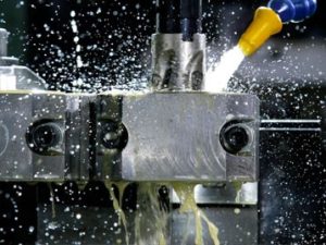
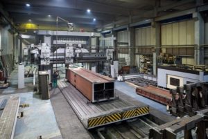 general cutting operations (e.g. lathes) the workpiece rotates whilst the cutting tool is stationary. Metal may also be removed by means of linear instead of rotational movement. In these operations, the workpiece and cutting tool move in a straight line relative to each other. The photo on the right shows such a machining operation. The cutting head (in the red rectangle) is attached to the light grey frame and can move up, down or to the left and right on slideways. The brown workpiece is fixed to a traverse table that moves backward and forward, also on slideways. The operator (with green pants) is visible on the left side of the photo. These metalworking machines can vary in size from modest basic units that produce small metal components to massive monsters designed to machine very large workpieces such as marine engines and mining machinery.


")
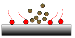
 Fig 2: Dispersants hold deposits in suspension.


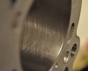
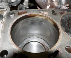
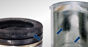
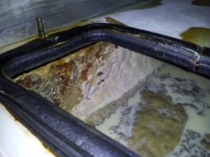
 Bore polishing is brought about by a build-up of carbon deposits in the piston top ring land area, i.e. the part of the piston above the top ring (Photo 3). Poor combustion of diesel fuel leads to these hard carbon deposits, which are highly abrasive and scrape away the honing grooves on the cylinder bores. Bore polishing leads to increased oil consumption (blue exhaust smoke) and loss of combustion pressure. This is because the oil film trapped in the honing grooves that maintains the piston ring seal and combustion pressure, is no longer there. Unburned fuel and combustion gases then leak past the piston rings and contaminate the lubricating oil.