Rheology is the science of flow and deformation of matter and describes the interrelation between force, deformation and time. Rheology is applicable to all materials, from gases to solids. Fluid rheology is used to describe the consistency of liquid matter by referring to viscosity and elasticity. Viscosity is the resistance to flow or thickness and elasticity relates to stickiness or structure.
Newtonian behaviour is a phenomenon that is firmly embedded in the science of Rheology and is also a key property that affects the performance of lubricants.
NEWTONIAN substances are matter of which the viscosity does not change with shear/stress or rate of flow. Typical examples of Newtonian fluids are water, alcohol and oil.
NON-NEWTONIAN materials are liquids or gels of which the viscosity does change when subjected to stress. Non-Newtonian fluids may thin down or thicken up when sheared or stressed as discussed below:
Thixotropy is the property of certain fluids and gels to become thinner when a constant force is applied, and after removal of the force the viscosity recovers fully to the initial state in a finite period of time. The higher the force that is applied, the lower the viscosity becomes. Thixotropy is a time-dependent phenomenon, as the viscosity of the substance must recover within a certain timeframe when the applied force is removed. Tomato sauce is a typical example. It is usually quite thick, leaving you frustrated waiting for it to run out of the bottle. In response you shake it, giving you that red shower that drowns the fries on your plate. Reason is that tomato sauce is thixotropic. Its thickness and viscosity decrease depending on for how long and how fast you shake it. When you allow the tomato sauce to settle for some time it “gels” again.
In some materials the structural strength/viscosity decreases while shearing but the viscosity does not fully recover after an appropriate rest period. It remains thinner than the initial state which indicates that the structure does not recover completely. A typical example of this behaviour is yogurt. After stirring, the viscosity of yogurt remains thinner than it was initially. Such substances may be classified as non-thixotropic.
Rheopexy is the rare property of some Non-Newtonian fluids to show a time-dependent increase in viscosity; the longer the fluid undergoes shearing forces, the higher its viscosity becomes. Rheopectic fluids, such as cream, thicken or solidify when stressed. Fresh cream usually flows readily, but when you shake or whip it long enough, its consistency changes, it stops to flow and eventually becomes solid. In summary, Rheopectic fluids thicken when subjected to shear forces.
In the next issue of OilChat we will discuss the significance of rheology in lubrication. If you have any questions about rheology (or any other lubricant related issues) in the interim, you are welcome to email us at info@bcl.co.za.


 In the sample on the left all the oil and water are demulsified.

 The test rig simulates a misaligned gear set operating in the test lubricant. The gears are loaded in 12 increasing “stages”. Tooth-wear is examined after each stage. The performance of the fluids is determined by the load stage at which excessive wear occurs. A high pass load stage indicates better resistance to wear. If failure does not occur at load stage 12, it is reported as >12.


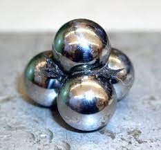 Four-Ball Weld Load Test. This procedure (ASTM D2783 for lubricating oils and ASTM D2596 for greases) evaluates the load-carrying (Extreme Pressure) properties of lubricants. During the test, the top ball rotates at 1760 rpm against the three stationary balls and the load is gradually increased until the lubricant fails. This happens when welding between the balls is detected (as depicted on the left). The weld point is the lowest applied load in kilograms at which the rotating ball welds to the three stationary balls.
 Four-Ball Wear Scar Test. This test measures the wear preventing properties of lubricants, using ASTM method D2266 for greases and D4172 for lubricating oils. The rotational speed of the top ball is 1200 rpm and is pressed with a force of 40 kg onto the three clamped balls. The temperature of the test lubricant is regulated at 75°C and the duration of the test is 60 minutes. Lubricants are compared by using the average size of the scar diameters worn on the three lower clamped balls. An enlarged 1,87 mm diameter wear scar is shown on the right.
 In addition, the contact between the balls is a sliding interaction. This combination is rarely found in machinery, where the most severe combinations are line contact with sliding (as in gears or journal bearings as illustrated on the left) or point contact with rolling (as found in ball bearings). This confirms that the test rig does not accurately simulate real-world contacts.


 GEAR COUPLINGS compensate for misalignment via the clearance between gear teeth. Shaft-mounted external gear teeth on both shafts mate with internal gear teeth on a housing that contains a lubricant. Another design mesh external teeth on one shaft with internal teeth mounted on the other shaft.
 CHAIN COUPLINGS operate similarly to gear couplings. Sprockets on each shaft end are connected by a roller chain. The clearance between the components, as well as the clearance in mating the chain to the sprockets, compensate for the misalignment. Loading is similar to that of geared couplings.


 The input power (usually from an electric motor) is applied to the worm gear. The rotation of the spiral ‘screw’ on the worm pushes the teeth of the wheel forward and rotates it as depicted by the animation on the left. A worm gear set can have a massive reduction ratio with little effort. Worm drives normally consist of a brass or bronze wheel and a steel worm. The wheel is designed to be sacrificial because it is normally cheaper and easier to replace than the worm itself.