TIMKEN OK LOAD #OilChat 93

Timken OK Load is a measurement that indicates the possible performance of extreme pressure (EP) additives in lubricants. In the Timken EP Test a standardized bearing race is rotated against a steel test block, as shown on the left. The contact area is flooded with the grease or oil that is being tested. Increasing loads are placed on the test block until a score mark is made on the test block. The load immediately before the score mark is made, is reported as the Timken OK load.  The units of measurement are pounds-force or kilograms-force.

When reviewing the technical data sheet for a lubricant or the lubricant specifications for a piece of equipment, you will often see reference to the Timken OK Load Test. So what does it mean when one lubricant has a 35 pound Timken OK Load rating and another has a 40 kg Timken OK Load rating? The truth is … it may have very little relevance to the amount of EP protection you are getting.

There are basically three reasons for this:

  1. The Timken Test Machine was designed by the Timken Bearing Company in 1935 and manufactured until 1972. Timken used the machine to confirm that extreme pressure chemistry in the cutting oils they were using (to manufacture bearings) was still working. It was never designed to quantify performance in any terms other than pass or fail with a 35 pound load applied. Large wear scars or scoring represented a fail and smooth scars were a pass. The test was later adopted by the lubricants industry when Timken began selling the machines. The American Society for Testing and Materials published the ASTM D-2509 procedure for testing greases and ASTM D-2782 for testing oils. From that point on manufacturers started competing for bragging rights to the highest Timken OK Load rating. The Timken test became a marketing tool rather than a simple indicator of the presence of EP additives. The Timken Bearing Company attempted to clarify the misunderstanding about the test with the following statement,“It was generally assumed that the higher the O.K. value, the more load the lube could hold without the film strength being compromised. However, this is not necessarily the case, and the primary purpose of the test is to determine whether or not the lube has an EP additive. Values higher than 35 lbs. indicate the presence of an EP additive.”
  2. There are certain EP additives that can be added to lubricants to give very high Timken results. However, no correlation has ever been established between these extraordinarily high Timken OK Loads and actual field performance. In fact, some of the additives that produce such high Timken OK Loads can be corrosive and/or hazardous and may damage the equipment they are formulated to protect.
  3. In terms of scientific testing, the Timken OK Load test has very poor repeatability and thus a wide margin of error. In fact, the official ASTM D-2509 Timken test procedure states that the results from one test to the next of the same lubricant on the same Timken machine can vary as much as plus or minus 23%. This means a lubricant that gets a pass rating at 60 pounds could actually be anywhere from a 46 pound load to a 74 pound load. If the same product is tested on a different machine, the rating can be off by plus or minus 59%, which means it could actually be anywhere from a 25 pound load to a 95 pound load. The poor repeatability of the test makes it possible for a lubricant manufacturer to repeat the test until the highest result is found and claimed. There are also many modified versions of the Timken machine used by some marketers to “demonstrate” load carrying properties. These are not accepted tests for determining EP properties as the results can easily be manipulated.

Most lubrication engineers and industry professionals agree that the Timken Test should only be used to indicate whether EP agents are present without implying anything about relative performance levels. Most equipment manufacturers now specify more relevant tests that have proven direct correlation to actual field experience (such as the Four Ball EP Weld Test, the  FZG Gear Tests and others) to indicate precisely how much EP and anti-wear performance they require of a lubricant.

So, how much EP is enough? What if grease “A” quotes a 100 pound Timken OK Load pass rating and a 400 kg 4-Ball Weld Load and Grease “B” quotes a 60 pound Timken OK Load pass rating and a 800 kg 4-Ball Weld Load. Which one would perform better in extreme pressure applications? The Timken OK Load ratings tell you that both greases have EP chemistry, but the 4-Ball Weld tells you grease “B” (even with the lower Timken OK Load rating) has the more effective EP chemistry.

In summary, do not let extreme Timken OK Load ratings over-influence the selection of lubricants. Actual field performance, other EP and performance tests (such as corrosion protection and oxidation resistance) may have far greater relevance in many applications.

Q8 offers a comprehensive range of extreme pressure lubricants for a wide variety of automotive, construction, industrial, mining, agricultural and other applications. For more information about the complete range of Q8 lubricants, phone 011 462 1829, email us at info@bcl.co.za or visit www.bcl.q8oils.co.za.

Flexible Coupling Lubrication Cleanliness

FLEXIBLE COUPLING LUBE CLEANLINESS #OilChat 92

Oil Chat 92

Couplings are used to join two shafts to transmit rotation and power from one shaft to the other. A typical example is the coupling between an electric motor and water pump as shown on the right. In an ideal world components can be installed in perfect alignment. Rigid couplings are generally used in applications with precise alignment.

In the real world, however, alignment is seldom perfect. Misalignments can be one of several fundamental types, including lateral, axial, angular or skewed/angled. The greater the misalignment the less efficient the motor is in generating speed and torque. Misalignment also contributes to premature wear, broken shafts, bearing failure and excessive vibration.

Flexible couplings are used extensively to compensate for misalignment between components. These couplings range from simple designs (e.g. an elastic element between two shafts) to intricate couplings such as constant velocity (CV) joints. The following metal-to-metal flexible couplings are commonly used in industrial applications:

Gear couplingGEAR COUPLINGS compensate for misalignment via the clearance between gear teeth. Shaft-mounted external gear teeth on both shafts mate with internal gear teeth on a housing that contains a lubricant. Another design mesh external teeth on one shaft with internal teeth mounted on the other shaft.


Chain CouplingCHAIN COUPLINGS operate similarly to gear couplings. Sprockets on each shaft end are connected by a roller chain. The clearance between the components, as well as the clearance in mating the chain to the sprockets, compensate for the misalignment. Loading is similar to that of geared couplings.

Grid Coupling


GRID COUPLINGS use a corrugated steel grid that bends to compensate for loading induced by misalignment. Grooved discs attached to the ends of each shaft house the grid, which transmits torque between them. Low amplitude sliding motion develops between the grid and grooves as the grid deforms under load, widening in some locations and narrowing in others over each revolution.

Unless specifically mentioned by the manufacturer, metal-to-metal couplings are generally grease lubricated. Coupling components are protected primarily by an oil film (which is released from the grease) and seeps into the loading zone to lubricate the metal contact surfaces. Greases formulated with high-viscosity base oils, anti-scuff additives and metal-wetting agents are recommended to overcome the boundary lubrication conditions that often exist in flexible couplings. High oil viscosity also reduces leakage rates.

Centrifugal forces in flexible couplings can be severe, becoming even more extreme as the rotational speed and the diameter of the coupling is increased. Even moderately sized couplings can generate centrifugal forces thousands of times greater than gravity (commonly referred to as G-force).  Centrifugal forces have a centrifuge effect on the grease inside flexible couplings. If a general purpose grease (in which the thickener is of higher density than the oil) is used, the thickener and the oil may separate – similar to a cream separator that splits the heavier milk from the lighter cream. One problem with separation of the oil and thickener is that the oil will tend to leak out of the coupling. A much greater problem, however, is that the thickener which is separated out, is moved by centrifugal force to the outer part of the coupling and against the torque transmission elements (e.g. the gear teeth in a geared flexible coupling). The thickener coats the transmission elements and keeps the oil component of the grease from lubricating them.

Blue Chip HSC 350 High Speed Coupling Grease is specifically formulated to resist separation of the oil, even under the high centrifugal forces encountered in couplings. This ensures reliable coupling lubrication over extended periods, even during high speed operation. For more information about HSC 350 High Speed Coupling Grease and the complete range of Blue Chip greases, phone 011 462 1829, email us at info@bcl.co.za  or visit www.bcl.q8oils.co.za.

WORM GEAR LUBRICATION #OilChat 91

Worm gears have been used for many centuries. In fact, their existence was described by Archimedes around 250 BC. Worm gear drives are different from all other types of gears.  They consist of a spirally grooved screw that engages with and drives a toothed wheel (the worm wheel or gear). By nature of their design worm drives can achieve large reductions in speed in a compact space. It changes the rotational movement by 90 degrees, and the plane of movement also changes due to the position of the worm on the worm wheel as shown on the right.

The input power (usually from an electric motor) is applied to the worm gear. The rotation of the spiral ‘screw’ on the worm pushes the teeth of the wheel forward and rotates it as depicted by the  animation on the left. A worm gear set can have a massive reduction ratio with little effort.  Worm drives normally consist of a brass or bronze wheel and a steel worm. The wheel is designed to be sacrificial because it is normally cheaper and easier to replace than the worm itself.

Worm gear drives have several advantages over other gear types. The two primary ones are:

HIGH REDUCTION RATIO. Worm gears can achieve reduction ratios ranging from 20:1 to 300:1. You can use it to reduce speed significantly and at the same time increase torque considerably. It will take multiple reductions of a conventional gearset to achieve the same reduction level of a single worm gear set. Worm gears therefore have fewer moving parts and less chances of failure.

SELF-LOCKING. With standard gears the output shaft can also turn the input shaft. This necessitates adding a backstop to a traditional gearbox (to prevent reverse rotation) which increases the complexity of the gear set. With worm drives it is practically impossible to reverse the direction of power since it is unlikely that the worm wheel will rotate the worm. The compact size and inability of worm gears to reverse the direction of power (self-locking) render them particularly suitable for many lift/elevator and escalator drive applications. The least complicated form of worm gears is those that are used to tune stringed musical instruments.

There is one particularly obvious reason why one would not choose a worm gear drive over a standard gear set and that is sliding friction. With standard gear types (spur, bevel, spiral bevel, helical and hypoid) the gear teeth slide and roll on each other when they mesh. The rolling action helps to distribute the lubricant on the teeth of the gears. With worm gears the contact is predominantly of a sliding nature. As the worm slides across the teeth of the wheel, it rubs most of the lubricant off. The result is that the worm is in contact with the wheel in a boundary lubrication regime (see OilChat 22).

The high rate of sliding in worm gears results in significant frictional heat build-up. This demands the use of high viscosity lubricants, typically ISO 460 or 680 viscosity grade and even ISO 1000 in severe applications. Traditionally compounded gear oils have been used extensively in worm gears with great success in a wide variety of applications. These are mineral oils with rust and oxidation inhibitors and tallow or synthetic fatty acid (the compounding agent), giving excellent lubricity to minimize sliding wear.

In days gone by gear oils that contain active extreme pressure (EP) additives were not recommended for worm gears. There was a concern that the sulphur-phosphorous EP additives would react with the brass or bronze gear wheels. Modern non-active sulphur EP additive technology, however, has eliminated corrosive attack of the worm wheel. EP gear oils work particularly well when shock loading occurs and also protect steel gears better than compounded gear oils.

Q8Oils offers a comprehensive range of high-quality gear lubricants for a wide variety of automotive, construction, industrial, mining,  agricultural and other applications. For more information about the complete range of Q8 lubricants, phone 011 462 1829, email us at info@bcl.co.za  or visit www.bcl.q8oils.co.za.

LUBRICANT CONTAMINATION #OilChat 90

We have discussed the importance of lubricant cleanliness in previous issues of OilChat but some topics justify emphasis and should be revisited from time to time. Lubricant contamination is one such subject. While there is much focus on using the correct lubricant, keeping the lubricant clean in storage, during decanting and the filling process and in operation is just as important. In fact, it does not matter how good a lubricant is, if it is contaminated with foreign matter and debris, it will affect the useful life of the lubricant and the equipment detrimentally.

Machine and equipment maintenance starts in the oil store. Lubricants are prone to contamination from the moment a new oil container arrives on your premises. The following measures can reduce and even prevent contaminants from entering your lubricating oil and grease:

Storage. Water and other contaminants can enter your lubricants due to storage conditions. This occurs when oil drums expand and contract during storage, allowing water, dirt, and dust to penetrate through the gaps of the closure threads. If at all possible, store your lubricants in a dry and clean area that is protected from extreme weather conditions. There are however measures you can take to prevent or minimize contamination, even when logistical difficulties make it impossible to store oil drums in ideal storage conditions. It is possible, for example, to store drums on their sides instead of vertically to prevent water and dust from collecting around the bungs.

Transfer. When a decanter is used to transfer oil make sure it is clean and does not contain any other lubricant. In many cases dispensing equipment like hoses, pumps and nozzles are used to transfer the lubricant rather than pouring it from the drum. The cleanliness of all the components in this procedure is essential to prevent contamination. It is great to have the proper specialised tools for each type of oil, but you must still maintain meticulous cleanliness. If leftover oil is left behind after use, it will contaminate the fresh oil during the next use.

Filling. You can introduce contamination when topping up or when changing oil. To prevent dirt from entering the machine, filtering the oil is a good practice. An often overlooked part of the service procedure is the condition under which you add the fresh oil. Make sure the filler point is clean before you open it. When changing oil, the used oil always has a degree of oxidation, which negatively affects the useful life of the new oil. You must therefore extract as much of the old oil as possible before adding the new oil.

In Service. All lubrication systems are susceptible to contamination. Water and dirt can enter the oil through any opening such as a badly fitting filler cap, a loose inspection lid, an uncapped filling point, a busted seal or an open or damaged vent. Condensation is another common way for water to get into the oil – lubricating systems subjected to high temperature variations in particular. Equipment and machinery operating in direct sunlight are especially vulnerable to condensation when cooling down during the night.

Contaminants in lubricating oil can also be the result of machine operation. Wear metals are the consequence of frictional wear or corrosion of machine components. The presence of these particles may correspond to normal wear patterns (depending on the nature and quantity of the particles). Conversely, they may be a sign of a machine that is failing. Lubricant analysis is valuable to gain clarity regarding the type of oil contamination and wear patterns. With this data one can make better decisions on preventative measures to improve machine reliability. It can also reduce cleaning and filtration costs by enabling you to optimize your systems according to your specific contaminants. You will also benefit from the prevention or reduction of downtime, as the data can act as an early diagnosis of a machine malfunction.

Oil contamination normally has dire consequences for machinery. It is therefore vital to take measures to prevent contamination wherever possible. While not all forms of contamination are avoidable, the above steps can minimize the risk. By ensuring you are using the correct lubricants, keeping your oils clean and implementing a lubricant analysis program, you can reduce the possibility of oil-related failures. Even small efforts can be effective in preventing costly problems down the road.

At Q8Oils we have the people, products and proficiency to assist you in reducing downtime and  optimizing equipment life. Simply phone 011 462 1829 or email us at info@bcl.co.za. Our lubricant experts will be happy to answer any questions you may have.

LUBRICANT CONSOLIDATION pt3 #OilChat 89

In this final part of the Lubrication Consolidation series we conclude with a further discussion of plant-based lubrication recommendations.

Many new products in the growing aftermarket lubricant industry offer comparable or superior quality to OEM-recommended lubricants. These products often undergo rigorous testing and certification processes to ensure they meet or even exceed relevant industry standards. Additionally, some aftermarket lubricants are specifically formulated to address issues commonly found in certain types of machinery and offer tailored solutions that OEM products may not provide.

What are the motives for selecting a lubricant for a machine? For service technicians, the primary concern may be to find a readily available “approved lubricant”. Although maintenance managers and plant engineers may share this requirement, they are likely more focused on how lubricant choices enhance equipment reliability. In addition operation supervisors, inventory clerks and plant managers, may each have unique considerations and their own perspective on how it impacts costs.

There is, however, more to this decision-making process. Quite often there are special considerations for environmental impact, necessitating environmentally acceptable lubricants or industry-specific needs, like food-grade lubricants in food and beverage facilities. Moreover, the common belief that using alternate lubricants automatically voids warranties is a myth, provided these lubricants meet the required specifications.

The complexities of maintenance culture, and the impact of lubricant selection on plantwide reliability, make lubricant selection much more than just a technical decision. This is a shift in how we see lubricants as vital assets that significantly impact the efficiency and longevity of machinery. Operators and maintenance managers can make more informed decisions based on the lessons learned here. Their decisions may have the potential not only to improve equipment performance and lifespan, but also to minimize operational costs.

Finally, lubricants must be viewed as something with economic value and the expectation that it will provide benefits. Many organizations that have focused on this as a proactive measure have documented savings in their maintenance budget and increased uptime of machines.

At Q8Oils we specialize in lubrication recommendations and offer a wealth of expertise when tailoring lubricants to specific operational needs – an aspect sometimes overlooked in OEM recommendations. Should you require assistance with your lubrication standardisation program simply email us at  info@bcl.co.za. We have the people, products and proficiency to consolidate your lubricant requirements.

Reference:
Bennet Fitch: Warning! The OEM-Recommended Lubricants Might Not the Best Choice, Machinery Lubrication Magazine: November 2023.

oilchat88

LUBRICANT CONSOLIDATION pt2 #OilChat 88

oilchat88

In this three-part series of our newsletter we compare the significance of OEM lubricant recommendations to plant based lubricant selection. In the previous issue of OilChat we examined the underlying objectives and considerations behind the OEM’s lubricant recommendations. In this issue of the newsletter we will  focus on the unique environment and operating conditions of the plant.

In this three-part series of our newsletter we compare the significance of OEM lubricant recommendations to plant based lubricant selection. In the previous issue of OilChat we examined the underlying objectives and considerations behind the OEM’s lubricant recommendations. In this issue of the newsletter we will  focus on the unique environment and operating conditions of the plant.

Plant specific lubricant selection is based on several considerations, including the following key areas:

Lubricant Consolidation:

Imagine a restaurant allows its customers to customize their meals. While this approach caters perfectly for the taste of each individual, it would require the restaurant to stock an enormous variety of ingredients and the cooking process will be significantly complicated. This could lead to inefficiencies, increased costs, longer waiting times and potential errors in order fulfilment.

In contrast, consider a restaurant with a well-planned menu. This menu may not cater for every specific customer’s preference, but it offers a balanced variety of dishes that satisfy the majority of patrons. By doing so the restaurant operates more efficiently and the kitchen can manage stock better, prepare meals faster and maintain a higher quality and consistency, all while reducing costs and complexity.

This scenario mimics the situation in a large plant with numerous machines. If each machine uses an OEM-recommended lubricant, the variety (like the customizable menu) becomes unmanageable and will lead to logistical challenges and increased costs. However, by selecting a consolidated list of lubricants (like a set menu), the plant can adequately meet the needs of most machinery. This approach enhances overall operational efficiency, simplifies inventory management and reduces costs – even if some machines have their  specific lubricant. In addition, more favourable lubricant supply agreements can be negotiated with suppliers which can provide immediate cost savings. The biggest savings, however, may be from reduced machine failures associated with cross-contamination and when the wrong product is used accidentally.

Optimum Lubricant Selection:

Like most other maintenance decisions for a machine, durability, safety, cost, and environmental impact will influence lubricant selection. This means that many similar machines may require different lubricants and service practices, all based on what is optimal to meet reliability objectives of the OEM.

The OEM-recommended lubricant is often a single lubricant (or specification) that considers the most intended use case. Nonetheless, any one machine may have different operating environments. For example, one specific machine may operate sufficiently with a straightforward economical lubricant. In contrast, in another area of the plant, the same type of machine may require a premium lubricant. In this case the most cost-effective lubricant, meeting the requirements of both machines, should be selected.

Upgraded Lubricant Selection:

Lubricant technology is constantly evolving. New formulations and additives are developed regularly to offer enhanced performance characteristics, such as better temperature stability, improved wear protection and extended lubricant life. In some cases newer aftermarket lubricants may outperform the products recommended by the OEM, especially in harsh or unusual operating conditions.

When considering specific operating conditions of a machine, lubricants need meticulous selection. Operating temperature, workload, and operational frequency are fundamental factors that can significantly affect lubricant performance. These can be counteracted with adjustments in lubricant selection, such as viscosity (which may be influenced by operating temperature and load) or lubricant formulation (this can improve oxidative stability, wear protection and seal compatibility).

In the next issue of OilChat we will discuss plant based lubricant selection in further detail. If you have any questions concerning lubricant consolidation in the interim, simply mail us at info@bcl.co.za. Our experts are at your disposal and ready to provide you with advice and guidance.

This approach may be adequate at first. However, several shortcomings require a more strategic approach, particularly when considering the specific environment and operating conditions of the plant, as well as the typical challenges of managing maintenance across dozens of machines. In this case the “safe choice” may have far-reaching implications that influence lubricant selections.

In the next issue of OilChat we will  focus on the lubrication requirements of the environmental and operating conditions of the plant. If you have any questions concerning lubricant consolidation in the interim, simply mail us at info@bcl.co.za. Our experts are at your disposal and ready to provide you with advice and guidance.

Reference:
Bennet Fitch: Warning! The OEM-Recommended Lubricants Might Not the Best Choice, Machinery Lubrication Magazine: November 2023.

OEM

LUBRICANT CONSOLIDATION & STANDARDIZATION #OilChat 87

OEM

Common belief is that to follow the lubricant recommendation of the Original Equipment Manufacturer (OEM) when servicing machinery in an industrial plant is the safest and most effective route. This opinion originates from trust in the OEM’s knowledge of their machine. In this three-part series of our newsletter we debate whether it is universally applicable – especially in large industrial plants. To answer this question, we will delve into two critical areas. In this issue of OilChat we will examine the underlying objectives and considerations behind the OEM’s recommendations.

OEM lubricant recommendations are based on several considerations, including the following key areas:

Machine Design and Operating Requirements: OEMs select a lubricant to match the machine design needs and test the lubricant under specific conditions with focus on reliability and durability. Operating conditions will include factors like temperature, load conditions, speed and environmental factors such as dust and moisture.

Industry Standards and Certifications: Lubricants must often meet certain industry standards or certifications and may require extensive lab testing and validations for performance in specific equipment categories.

Warranty Liability Concerns and Other Commercial Factors: Recommended lubricants are often a stipulation for maintaining a warranty. This requirement stems from the OEM’s confidence in specific lubricants. OEMs frequently sell these lubricants directly, sometimes under their own brand.

Overall Ease of Maintenance and Cost-Efficiency: OEMs consider the balance between the cost of the lubricant and the overall cost of operation and maintenance. The goal is to recommend a lubricant that provides cost-effective operation over the lifespan of the equipment.

Selecting one lubricant for a specific machine is easy. For smaller plants, the lubricant is a minor cost. The answer is therefore normally to simply use the OEM-recommended lubricant. For larger plants, lubricants are a much more substantial expenditure and one bad choice could cost the organization significantly in repair and downtime. It is, therefore, often the same answer – the OEM recommendation.

This approach may be adequate at first. However, several shortcomings require a more strategic approach, particularly when considering the specific environment and operating conditions of the plant, as well as the typical challenges of managing maintenance across dozens of machines. In this case the “safe choice” may have far-reaching implications that influence lubricant selections.

In the next issue of OilChat we will  focus on the lubrication requirements of the environmental and operating conditions of the plant. If you have any questions concerning lubricant consolidation in the interim, simply mail us at info@bcl.co.za. Our experts are at your disposal and ready to provide you with advice and guidance.

Reference
Bennet Fitch: Warning! The OEM-Recommended Lubricants Might Not the Best Choice, Machinery Lubrication Magazine: November 2023.

tribology

TRIBOLOGY #OilChat 86

tribology

Tribology (from the Greek word ‘tribos’ meaning rubbing) can be described as the science of friction, wear and lubrication of interacting surfaces in relative motion to one another. Peter Jost, a British mechanical engineer, can be considered the founder of the discipline of tribology. In 1966 he published a report which highlighted the cost of friction, wear and corrosion to the British economy. It was in this report that the term tribology was originally used. The earliest systematic studies of tribology were, however, performed by Leonardo da Vinci, the first tribologist of the world, more than 500 years ago. He did not publish any of his findings but some of his notebook pages discovered more recently, contain amazing illustrations and observations related to friction.

FRICTION: Our ancestors first became familiar with friction in the Stone Age, when they discovered that they could create fire by rubbing pieces of wood against each other. We do not know for sure exactly when they mastered the art of making fire, but indications are that it was approximately 400,000 years ago. Leonardo da Vinci (1452 -1519) studied friction for more than 20 years of his life and understood very well that friction was a limiting factor in the design of his ‘revolutionary’ machines. He distinguished between various types of friction (the force that opposes the motion of a solid object over another) and noted that surface roughness has an impact on how easy it is to move different materials in contact with one another.

There are primarily four types of friction:

Static Friction is the frictional force between contacting surfaces when they are at rest with respect to each other. The magnitude of the static force is equal to and in the opposite direction of a force applied to move one surface. The maximum static friction is reached just before the surface starts to move.

Sliding Friction occurs when the surface of one object moves relative to the surface of another object. It is also called Kinetic Friction and it is the force required to keep a surface sliding over another surface.

Rolling Friction is defined as the force which resists the rolling motion of a round object (ball or wheel) over a surface. Rolling Friction is lower than Static and Sliding Friction.

Fluid Friction occurs between the layers of a fluid that are moving relative to each other. This internal resistance to flow is termed viscosity.

WEAR: Humankind has been faced with the problem of wear since the invention of the wheel more than 5000 years ago. Wear can be described as the removal of material from surfaces in sliding or rolling contact with each other. Wear is a universal phenomenon and rarely do two solid bodies slide over each other without a measurable material transfer or material loss, e.g. coins become worn as a result of continued contact with fabrics and human fingers. There are essentially three types of mechanical wear:

Adhesive Wear occurs during sliding when fragments of material are pulled off one surface and adhere to the other.  This is the most common and least preventable type of wear.

Abrasive Wear is caused by a hard surface (or hard particles) rubbing against a soft surface.  The hard material cuts and ploughs the opposing softer surface.

 Surface Fatigue Wear.  Repeated sliding or rolling over a surface causes subsurface cracks to initiate and grow and eventually lead to material breakup.  This generally occurs if all the other wear mechanisms are very low, such as in rolling element bearings.

 LUBRICATION: In a world that depends a great deal on machines, lubrication is absolutely essential. The science of tribology has advanced significantly in recent times, but the roots of lubrication extend back further than one might imagine. Lubrication in simple form has been in existence at least since the beginning of documented times.

lubricant is a substance introduced between two surfaces, which are in relative motion to each other, to reduce friction and wear between them. Most fluids, including water, can be used as a fluid lubricant in appropriate applications. In fluid lubrication, the lubrication regime is determined  by the type of lubricating film that is created and the degree of contact between two surfaces. The three distinct lubrication regimes between two sliding surfaces are Boundary Lubrication, Mixed Lubrication and Hydrodynamic Lubrication. In addition to these we also have Elastohydrodynamic Lubrication. It is the condition that occurs when a lubricant is introduced between surfaces that are in rolling contact, such as roller bearings. These lubrication regimes were discussed in detail in OilChat 22.

The early focus of tribology was to improve the efficiency and durability of machinery. Today tribology research extends to a much wider range of macro and nano disciplines in areas as diverse as  the movement of continental plates, biomedical materials, computers and robotics, alternative energies, and many more.

Q8Oils offers a comprehensive range of high-quality lubricants to reduce friction and wear in a wide variety of automotive, construction, industrial, mining and agricultural applications. For more information about the complete range of Q8 lubricants, phone 011 462 1829, email us at info@bcl.co.za  or visit www.bcl.q8oils.co.za.

brake fluid

DOT 3 vs DOT 4 Brake Fluid #OilChat 85

brake fluid

The U.S. Department of Transportation (DOT) classifies brake fluid into four main categories i.e. DOT 3, DOT 4, DOT 5 and DOT 5.1. The primary differences are their composition and boiling points. (We have discussed brake fluid in detail in OilChat 27 and suggest you revisit it to refresh your memory). Discussions in this newsletter will be restricted to DOT 3 and DOT 4 brake fluids.

Since 2006 DOT 4 is the most common brake fluid used in cars and light commercial vehicles. This is due to higher brake system temperatures, as well as widespread use of anti-lock braking systems (ABS), Electronic Stability Programmes (ESP) and traction control systems (TCS). Nonetheless some (mainly older) vehicles still require DOT 3, but since it is no longer readily available the question is often asked whether one can use DOT 4 instead of DOT 3 brake fluid. Unfortunately there is no straightforward answer to the question.

Both DOT 3 and DOT 4 brake fluids are glycol-ether based and therefore these fluids can be mixed without compatibility issues. Brake fluids are exposed to very high temperatures during braking and and the U.S. Department of Transportation have therefore included minimum boiling points in their Federal Motor Vehicle Safety Standards (FMVSS) 116 brake fluid specifications:

FMVSS 116 brake fluid specifications

There are no standard formulations for brake fluids, but DOT 3 generally includes about 80% glycol-ether while DOT 4 typically has 50 to 65% glycol-ether with 20-30% borate-ester to improve the high temperature characteristics of the fluid. And this is the reason for the confusion.

Older vehicles that are still on the road today may have had their brake systems designed before DOT 4 brake fluid was introduced. Some brake hoses used in these vehicles, particularly those with inner tubes made of SBR rubber, were found to be incompatible with certain DOT 4 formulations in laboratory testing. The suspect brake fluids appear to be ones with high borate-ester content. It is believed that these formulations permeate the inner tube and then react with the PVA reinforcement braiding to produce a viscous liquid which could build up between the layers of rubber and make the hose considerably weaker. Attempts to reproduce this problem in real life conditions have proven to be difficult though. Most vehicle manufacturers today, however, use a different rubber (EPDM) in their brake hoses which is much more resistant to permeation.

There are several 2006 and older vehicles on the road today that still operate perfectly with their original brake hoses, but when considering what can happen when brakes fail, it is better to be safe rather than sorry. Standard rubber brake hoses do not cost a fortune and are considered consumables, i.e. they need to be replaced. Most vehicle manufacturers recommend you do so at least every six years. This implies that the original brake hoses still fitted to 2006 and earlier vehicles are long overdue.

IMPORTANT: Glycol-ether based brake fluids are hygroscopic which means they absorb moisture from the atmosphere and need to be replaced at least every two years – see your vehicle owner’s manual. It is also important to remember that brake fluid is toxic and combustible and can damage the paintwork of your vehicle.

Boiling point for FMVSS 116

Blue Chip DOT 4 Brake Fluid is compatible with all materials used in the brake and clutch systems of late model vehicles and exceeds the boiling point requirements of FMVSS 116 as shown below:

If you have any questions about brake fluid, you are welcome to email us at info@bcl.co.za and one of our technical experts will respond to your query.

Kinematic vs Dynamic Viscosity #OilChat 84

Informally viscosity is known as the ‘thickness’ of a fluid. If you pour water into a container with a hole at the bottom, it drains in no time. However, if you fill the same container with honey, it drains much slower. Reason is that the viscosity of honey is high compared to that of water. You can therefore say the viscosity of a liquid is its resistance to flow.

Informally viscosity is known as the ‘thickness’ of a fluid. If you pour water into a container with a hole at the bottom, it drains in no time. However, if you fill the same container with honey, it drains much slower. Reason is that the viscosity of honey is high compared to that of water. You can therefore say the viscosity of a liquid is its resistance to flow.

More formally, viscosity is a measure of the internal friction of a fluid. Most liquids are cohesive. Cohesiveness is the intermolecular attraction by which the molecules of the fluid are held together and result in the internal friction of the fluid. This internal friction must be overcome by some force for the fluid to flow. A fluid with low viscosity flows easily because its chemical structure results in little friction when the molecules are in motion. There are various methods to measure the internal friction or resistance to flow, with the following two being the most frequently used for oil:

Kinematic Viscosity:

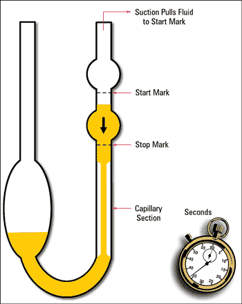
In kinematic viscometers the fluid flow is driven by gravity. This means the weight or density of the fluid helps it to flow. These viscometers measure the time that the fluid takes to flow through a capillary section in a viscometer tube. Each viscometer tube has a capillary constant. To obtain the kinematic viscosity, you multiply the measured flow time by the capillary constant. The unit for kinematic viscosity is centistoke (cSt). 1cSt equals 1 millimeter squared per second (mm2/s). The standard reference temperatures for kinematic viscosity measurements of lubricating oil are 40⁰C and 100⁰C

Dynamic Viscosity:

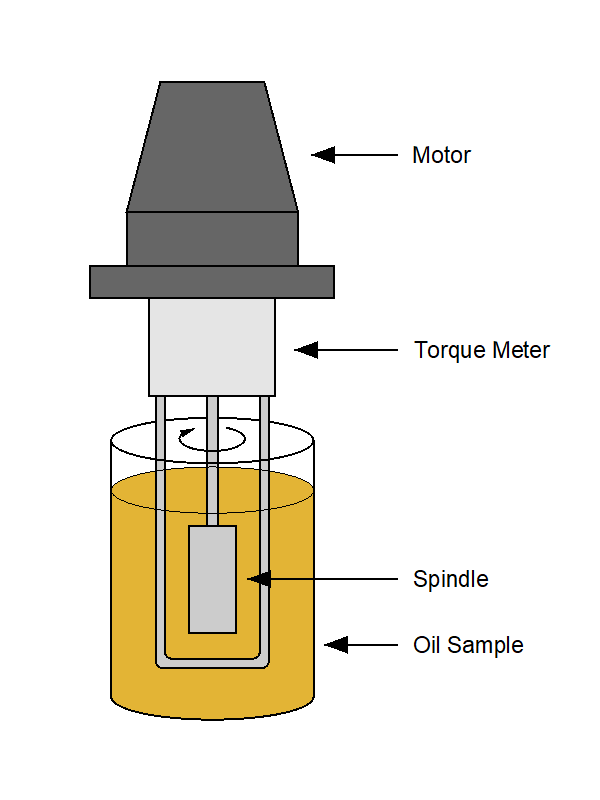
Fluid flow is induced by an external force in dynamic viscometers. Rotary viscometers are frequently used to measure the  dynamic viscosity of oil. The test oil, kept at a stipulated temperature, is poured into the viscometer sample container and a spindle is inserted in the oil. The spindle is rotated at a specified RPM and the torque required to maintain the RPM is measured. The results are reported in centipoise (cP). 1cP is equal to 1 millipascal-second (mPa-s). Pascal is a unit of torque similar to kW and HP. Dynamic Viscosity is also known as Absolute  Viscosity.


In summary of the above we can say that:

  • Kinematic viscosity is the internal resistance of the oil to flow and shear under gravity.
  • Dynamic viscosity refers to the resistance of the oil to flow when an external force is applied.

Simply put, kinematic viscosity indicates how fast the fluid flows under gravity, while dynamic viscosity denotes what force is required to make the fluid flow at a certain rate. 

Kinematic viscosity incorporates fluid density as part of the measurement and therefore density provides a means to convert between kinematic and dynamic viscosity. The conversion formula is:

Kinematic Viscosity (cSt) x Density = Dynamic Viscosity (cP)

Kinematic or capillary viscometers are normally used to measure the viscosity of lubricating oils, typically at 40⁰C and 100⁰C. Rotational or absolute viscometers, however, are often employed for certain specific measurements. Multigrade motor oil is a typical example.

The viscosity grade of motor oil is specified by the Society of Automotive Engineers (SAE). Multigrade oils must conform to several viscosity requirements and their viscosity grade consists of two numbers, e.g. SAE 10W-40. The 10W represents the low temperature (Winter) specifications and the 40 specifies the high temperature requirements. The SAE Engine Oil Viscosity Standard J300 defines the limits for multigrade engine oils, using the following viscosity categories:

Kinematic Viscosity in cSt

  • Low-Shear Viscosity at 100⁰C

Absolute Viscosity in cP

  • Low-Temp Cranking Viscosity*
  • Low-Temp Pumping Viscosity*
  • High-Shear Viscosity at 150⁰C

*Temperature depending on viscosity grade.

In conclusion we emphasize that viscosity units of measure and viscometers are not restricted to what we have discussed above but we trust that this newsletter will clear some of the confusion around kinematic and dynamic viscosity.

If you have any questions about viscosity, you are welcome to email us at info@bcl.co.za