Demulsibility is a term commonly used in the language of lubrication. Demulsibility is the ability of oil to release or separate from water. In other words, it is a measure of how well the lubricant can resist emulsification. A high demulsibility rating means that the lubricant will resist forming an emulsion with water, while a low number indicates that it will not.
Oil and water separate readily because similar molecules attract each other, i.e. oil sticks with oil, water sticks with water. However, when a mixture of oil and water is agitated, an emulsion is formed. Three oils with various degrees of demulsification and emulsification are shown on the right:
 In the sample on the left all the oil and water are demulsified.
There is an interface (emulsion) of oil and water in the middle sample,In the sample on the right all the oil and water are emulsified.
In most instances the oil and water will separate completely when left to settle for an adequate period of time. The water drops to the bottom since water is denser than oil.
In lubrication the demulsification property of oil is a benefit since water shedding is important for systems that have the potential to become contaminated with water. Water that enters a circulating system and emulsify can increase wear and corrosion, reduce load-carrying capacity, promote oil oxidation, deplete additives and plug filters. In hydraulic systems it can also adversely affect the operation of valves, servos and pumps. Although highly refined oils permit water to separate readily, demulsibility can be affected negatively by the presence of impurities and contaminants in the oil. Some oil additives such as rust inhibiters and dispersants can actually promote emulsion formation.
The impact of demulsibility depends on the level of contamination and the residence time (the time the oil spends ‘resting’ in the reservoir) of the system. When the resident time is sufficient the demulsified water can be removed by engineering solutions such as drain valves, suction, etc.
Demulsibility testing can show failure in the lab, but with sufficient residence time, the oil may shed water at an acceptable rate that does not impact oil performance. Small oil reservoirs with lower residence times require better demulsibility performance than larger sumps. It is recommended that testing for demulsibility should be conducted on a regular basis if the oil system is exposed to water or if demulsibility performance is suspicious.
The ASTM D1401 demulsibility test method is commonly used to determine the ability of oil to separate from water. A 40 ml sample of the test specimen and 40 ml of distilled water are stirred for 5 minutes in a graduated cylinder at a specified temperature. The time required for the separation of the emulsion is recorded after every 5 minutes. If complete separation or emulsion reduction to 3 ml or less does not occur after standing for 30 minutes, the volumes of oil, water, and emulsion remaining are reported.
Regardless of what is said above, a few equipment manufacturers do not recommend hydraulic oils that shed water. Caterpillar hydraulic oil is for instance formulated to hold water in dispersion.
The oil contains emulsifiers specifically designed to disperse water. Caterpillar does not recommend oils that “separate,” “shed,” or “release” water. They claim that separated water drawn through the hydraulic system can damage pumps and other components. If the water freezes, it can also cause serious damage to hydraulic systems. Notwithstanding this many Caterpillar machines in mixed fleet operations are operating satisfactorily with lubricants that do demulsify or shed water.
Q8Oils offer a comprehensive range of demulsifiable lubricants for a wide variety of automotive, construction, industrial, mining, agricultural and other applications. For more information phone 011 462 1829, email us at info@bcl.co.za or visit www.bcl.q8oils.co.za.
Finally we would like to wish all our loyal followers a prosperous and rewarding 2025.


 The test rig simulates a misaligned gear set operating in the test lubricant. The gears are loaded in 12 increasing “stages”. Tooth-wear is examined after each stage. The performance of the fluids is determined by the load stage at which excessive wear occurs. A high pass load stage indicates better resistance to wear. If failure does not occur at load stage 12, it is reported as >12.


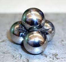 Four-Ball Weld Load Test. This procedure (ASTM D2783 for lubricating oils and ASTM D2596 for greases) evaluates the load-carrying (Extreme Pressure) properties of lubricants. During the test, the top ball rotates at 1760 rpm against the three stationary balls and the load is gradually increased until the lubricant fails. This happens when welding between the balls is detected (as depicted on the left). The weld point is the lowest applied load in kilograms at which the rotating ball welds to the three stationary balls.
 Four-Ball Wear Scar Test. This test measures the wear preventing properties of lubricants, using ASTM method D2266 for greases and D4172 for lubricating oils. The rotational speed of the top ball is 1200 rpm and is pressed with a force of 40 kg onto the three clamped balls. The temperature of the test lubricant is regulated at 75°C and the duration of the test is 60 minutes. Lubricants are compared by using the average size of the scar diameters worn on the three lower clamped balls. An enlarged 1,87 mm diameter wear scar is shown on the right.
 In addition, the contact between the balls is a sliding interaction. This combination is rarely found in machinery, where the most severe combinations are line contact with sliding (as in gears or journal bearings as illustrated on the left) or point contact with rolling (as found in ball bearings). This confirms that the test rig does not accurately simulate real-world contacts.


 GEAR COUPLINGS compensate for misalignment via the clearance between gear teeth. Shaft-mounted external gear teeth on both shafts mate with internal gear teeth on a housing that contains a lubricant. Another design mesh external teeth on one shaft with internal teeth mounted on the other shaft.
 CHAIN COUPLINGS operate similarly to gear couplings. Sprockets on each shaft end are connected by a roller chain. The clearance between the components, as well as the clearance in mating the chain to the sprockets, compensate for the misalignment. Loading is similar to that of geared couplings.


 The input power (usually from an electric motor) is applied to the worm gear. The rotation of the spiral ‘screw’ on the worm pushes the teeth of the wheel forward and rotates it as depicted by the animation on the left. A worm gear set can have a massive reduction ratio with little effort. Worm drives normally consist of a brass or bronze wheel and a steel worm. The wheel is designed to be sacrificial because it is normally cheaper and easier to replace than the worm itself.